The Electra Forums

Guitar Talk about Electra and other vintage imported guitars
Home
Index of Models
The Electra Forums
PM Inbox
It is currently Thu Nov 21, 2024 11:59 pm

All times are UTC - 8 hours


Post new topic Reply to topic  [ 41 posts ]  Go to page 1, 2, 3  Next
Author Message
PostPosted: Fri Apr 15, 2011 8:06 pm 
Offline

Joined: Wed Apr 13, 2011 5:47 pm
Posts: 22
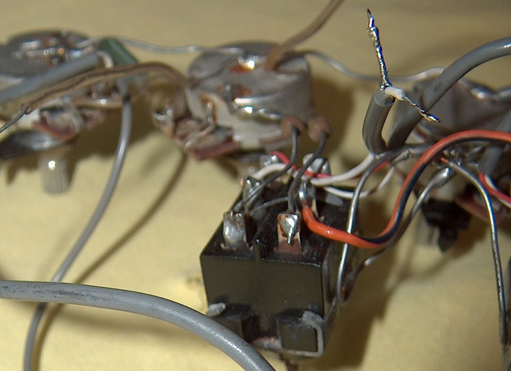
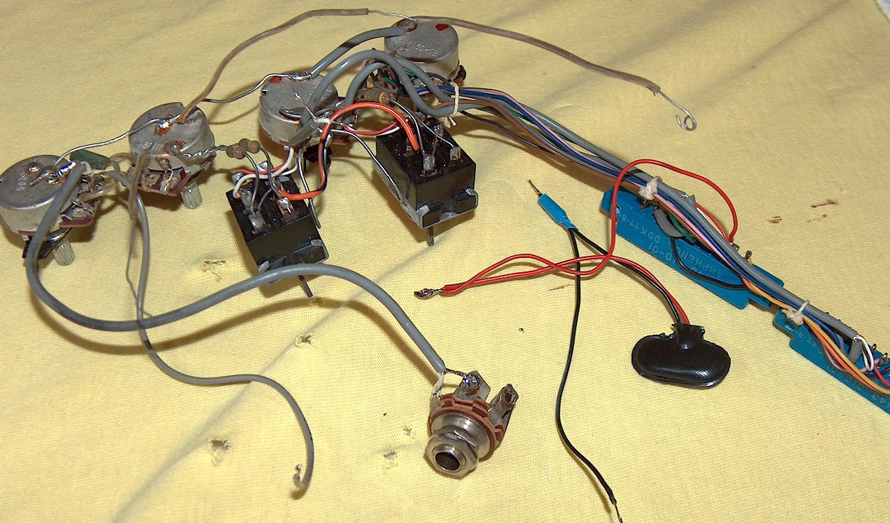
Hi! I'm new to the forum and this is my first post. I'm in need of some help rewiring my MPC X330. I bought it almost four years ago and stupid me ripped all the electronics out of it without taking any pictures or making any diagrams. :blush: Boy am I regretting it now. The guitar had no frets and binding was missing so I fixed it up and I'm ready to put it all back together. So far I have the ratory switch and the pickups installed. Thanks to the diagram here on this forum I was able to do that much. But now I have a bunch of wires that need to be soldered someplace and the diagram doesn't have any of these particular wires in it. I have taken about 7 or 8 pictures of the wiring but I can't figure out how to upload images.

Is there anyone out there willing to help me out? Maybe even talk me through it on the phone if that ain't too much trouble.

I posted this in the "Electra Guitar Discussion" forum as opposed to the Repair and Restoration forum because there seemed to be more activity on this one. If someone would be kind enough to tell me how to upload photos, I'd post them. Or I can e-mail them to anyone willing to help. Thanks!


Top
 Profile  
 
PostPosted: Fri Apr 15, 2011 8:21 pm 
Offline

Joined: Wed Apr 13, 2011 5:47 pm
Posts: 22
Well I found the how to upload pictures thread. I uploaded them and then went to post one but nothing shows up. Do the pic files have to be a certain size?

Image


Top
 Profile  
 
PostPosted: Fri Apr 15, 2011 8:23 pm 
Offline

Joined: Wed Apr 13, 2011 5:47 pm
Posts: 22
I figured it out but maybe I should have made the pics smaller. Sorry about that.


Top
 Profile  
 
PostPosted: Sat Apr 16, 2011 4:19 am 
Offline
User avatar

Joined: Mon Oct 27, 2008 7:10 pm
Posts: 3051
Location: Tifton, Ga USA
MCbrat has done a re wire on MPC I think so maybe he can help. The larger pic offers a better detail of the wires etc so no problem there. There should be round here I think. Looks like most of the wires are in tact so should not be to bad a job. The edge connectors take the most work other than the rotary switch so you should be OK. Hope to see her when you get done. Good Luck. :up:

_________________
Always give thanks for everyday, It may be your last so Rock On Semper Fi!!


Top
 Profile  
 
PostPosted: Sat Apr 16, 2011 4:40 am 
Offline

Joined: Thu Jun 17, 2010 1:50 pm
Posts: 1569
Location: New Jersey
Your Black battery wire goes to the input jack lug that your braided shield is soldered to. Your vol pot looks a little funny. The left lug should have the green chiclet on it. It should also be tied into the loose gray wire you have. The other end of the gray wire should go to the far middle lug of the far mpc switch. The middle lug on the vol pot should have only your lead to the input jack. Aside from that, you look to be in pretty good shape. Welcome to the forums and let us know how you make out. Radio shack has replacement mpc switches if you want to restore your switch tips.

Oh - and the loose wire from the top of your tone pot is the ground that goes under the control cover. The clipped gray lead on your 1st mpc switch should splice into your rotary switch. I think that's it.


Top
 Profile  
 
PostPosted: Sat Apr 16, 2011 4:51 am 
Offline

Joined: Wed Apr 13, 2011 5:47 pm
Posts: 22
Thanks Mortarman!

This next pic is another general pic of all the pots, wires and stuff. There are about 10 wires (including the ground wires) that need to go someplace and I know where a few of them go. Like I know one of those ground wires is a bridge ground....or really a tailpiece ground. I also know where to solder the output coming from the rotary switch.

Image


Last edited by nickc35 on Sat Apr 16, 2011 5:36 am, edited 2 times in total.

Top
 Profile  
 
PostPosted: Sat Apr 16, 2011 4:55 am 
Offline

Joined: Wed Apr 13, 2011 5:47 pm
Posts: 22
not sure why the 2nd pic did not work.

Image


Top
 Profile  
 
PostPosted: Sat Apr 16, 2011 5:15 am 
Offline
User avatar

Joined: Tue Dec 21, 2004 6:30 pm
Posts: 1763
Location: Central Iowa
all the diagrams I used/made are in the thread here...
viewtopic.php?f=15&t=4392&hilit=outlaw+150k

_________________
My Electra Pages
I have too many projects!


Top
 Profile  
 
PostPosted: Sat Apr 16, 2011 5:17 am 
Offline

Joined: Wed Apr 13, 2011 5:47 pm
Posts: 22
Jead wrote:
Your Black battery wire goes to the input jack lug that your braided shield is soldered to. Your vol pot looks a little funny. The left lug should have the green chiclet on it. It should also be tied into the loose gray wire you have. The other end of the gray wire should go to the far middle lug of the far mpc switch. The middle lug on the vol pot should have only your lead to the input jack. Aside from that, you look to be in pretty good shape. Welcome to the forums and let us know how you make out. Radio shack has replacement mpc switches if you want to restore your switch tips.

Oh - and the loose wire from the top of your tone pot is the ground that goes under the control cover. The clipped gray lead on your 1st mpc switch should splice into your rotary switch. I think that's it.


Jead - Thanks for your help but your post has me asking some more questions

- I have no braided shield soldered to any lug on the output jack. So I am still not sure which lug the black wire gets soldered to.

- the left lug of the volume pot (looking at the pot from the bottom) does indeed have the capacitor (chiclet) soldered to it. It's just hard to see in the pic. But I don't understand which loose gray wire it should be tied to. Basically I have 3 loose gray wires. 2 of those loose gray wires are actually sets of wires, a bare ground and a white wire. I know that the output from the rotary switch gets soldered to the short gray wire (white and bare ground) that is soldered to the first mpc switch. Then the other gray wire set (white and bare ground) gets soldered to the output jack....not sure what lugs on the output jack though.

Your comment about only one wire coming from the middle lug of the volume pot has me concerned. There are two gray wires coming from that middle lug.

the short story is, I'm still confused here


Top
 Profile  
 
PostPosted: Sat Apr 16, 2011 5:33 am 
Offline

Joined: Wed Apr 13, 2011 5:47 pm
Posts: 22
Now I'm frustrated that I can't post anymore pics. I did exactly the same thing as I did to post the first pic. Any ideas what I'm doing wrong. I feel like a big dummy. :blush:


Okay, so the black battery wire gets soldered to the ground lug on the output jack, right? So where does the red battery wire get soldered to?


Top
 Profile  
 
PostPosted: Sat Apr 16, 2011 5:53 am 
Offline
User avatar

Joined: Mon Oct 27, 2008 7:10 pm
Posts: 3051
Location: Tifton, Ga USA
If you would like I can post the pics for you. Send the pics to me at my email mortarman120gang@yahoo.com and I can get them posted in this thread. It can be tricky sometimes to get it just right. Always great to see another MPC restored to it's operational status again. :up:

_________________
Always give thanks for everyday, It may be your last so Rock On Semper Fi!!


Top
 Profile  
 
PostPosted: Sat Apr 16, 2011 5:57 am 
Offline
User avatar

Joined: Thu Feb 07, 2008 5:52 am
Posts: 1938
Location: Ann Arbor, Michigan
Change the .jpg to .JPG and it works, my camera (or software) does this too. Here they are:
Image
Image

My question is how are you going to shoehorn that in there already soldered up? Are the routes big enough? Best of luck, oh and Welcome aboard, Mike.

_________________
Electra Guitar Videos ===> http://www.youtube.com/user/mjm33mjm?feature=watch


Top
 Profile  
 
PostPosted: Sat Apr 16, 2011 8:21 am 
Offline

Joined: Thu Jun 17, 2010 1:50 pm
Posts: 1569
Location: New Jersey
Looks like you have a stereo input jack - why I don't know. The battery Black should be paired with the non white wire. Looks like you have a gray wire on the right lug of the vol pot. That should be paired with the chiclet on the left lug and from there to the right mpc switch mid right lug.
The middle lug of the v pot should have the hot lead to your output jack - the other lead on that wire should be soldered/grounded to the top of the v pot.

Here's pics of one of my 330's wiring. I'll check the other for consistency.

OK - my otherr 330 has a stereo jack and the battery blk is connected to what would be your unused lug on the input jack.
Your red battery wire goes to one of the MPC amphenols and looks fine as it is.
Image
Image
Image


Top
 Profile  
 
PostPosted: Sat Apr 16, 2011 9:06 am 
Offline

Joined: Wed Apr 13, 2011 5:47 pm
Posts: 22
Thanks for posting those pics.

Okay, I plugged in the soldering iron and did a few things. I took that 2nd gray wire coming out of the middle lug of the vol pot and fixed it by soldering it to the left lug of vol pot with the capacitor. Then I soldered the other end of that wire to the far middle lug of the far mpc switch. Then I connected the output from the rotary switch to the short gray wire with the bare ground and white wire coming out of it(in my pics). Then I took the output of the midde vol pot lug and soldered it to the output jack. The white wire went the hot/tip lug of the output jack and the bare ground went to the middle ground lug on the output jack. I also took care of the two ground wires coming off of the back of the volume pot. One is the string ground and the other is screwed down in the control cavity.

So this leaves the whole battery thing that I'm still unsure of. The red wire is connected to one of the module thingys (don't you love my techinical words) but there is still a mid point of that red wire that was soldered to something else before. You can see that in the picture. I just soldered the black battery wire to the ground lug on the output jack along with the bare ground coming from volume pot middle lug output. But maybe that was wrong, as was stated, maybe I should have soldered it to the 3rd (unused lug) on the output jack. Huh?

Thanks for the previous help. Some times this stuff can get so confusing. With passive guitar wiring I'm fine but as soon as you put active circuits in the mix, I'm lost.

SO....I'M ALMOST THERE....WHERE DOES THAT RED WIRE (MID POINT BETWEEN MODULE-THINGY AND BATTERY CLIP) GET SOLDERED TO??????


Top
 Profile  
 
PostPosted: Sat Apr 16, 2011 9:55 am 
Offline

Joined: Thu Jun 17, 2010 1:50 pm
Posts: 1569
Location: New Jersey
I don't think that red wire gets soldered anywhere. I think it's just an extension - just tape it up or desolder/resolder with shrink tube.

All I can tell you on the blk battery wire is that my stereo jack has it wired to what would be the unused lug in your picture.

Other than that, how the heck are you going to get the MPC amphenols back in place without cutting a big hole? Undo everything and re-connect? Are you good on all your wiring now?


Top
 Profile  
 
Display posts from previous:  Sort by  
Post new topic Reply to topic  [ 41 posts ]  Go to page 1, 2, 3  Next

All times are UTC - 8 hours


Who is online

Users browsing this forum: No registered users and 29 guests


You cannot post new topics in this forum
You cannot reply to topics in this forum
You cannot edit your posts in this forum
You cannot delete your posts in this forum

Search for:
Jump to:  
Powered by phpBB® Forum Software © phpBB Group