The Electra Forums

Guitar Talk about Electra and other vintage imported guitars
Home
Index of Models
The Electra Forums
PM Inbox
It is currently Thu Nov 21, 2024 2:01 pm

All times are UTC - 8 hours


Post new topic Reply to topic  [ 20 posts ]  Go to page 1, 2  Next
Author Message
PostPosted: Tue Dec 21, 2010 11:12 am 
Offline
User avatar

Joined: Tue Dec 21, 2004 6:30 pm
Posts: 1763
Location: Central Iowa
I went through my outlaw rebuild thread and pulled this stuff into a post here that I'll sticky....

MPC Wiring Diagram Updates.

Original Edge Connector diagram.
Image
Added the pin numbers.
Image

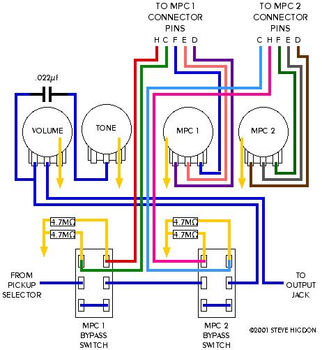
Original Steve Higdon Control Cavity Wiring Dagram
Image

Added pin numbers and corrected the diagram for the input/output pins (H & C) of module 2, and changed color coding to match the above diagram for the Module connectors for ease of wiring...
Image

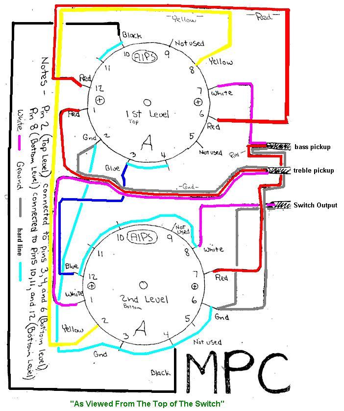
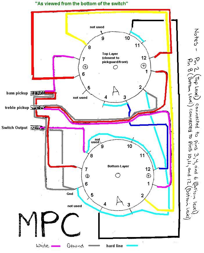
5-Way switch diagram. Colored and pin numbers added...
Image


Image


Image

_________________
My Electra Pages
I have too many projects!


Top
 Profile  
 
PostPosted: Tue Dec 21, 2010 11:59 am 
Offline
User avatar

Joined: Mon Oct 27, 2008 7:10 pm
Posts: 3051
Location: Tifton, Ga USA
Great stuff Thanks

_________________
Always give thanks for everyday, It may be your last so Rock On Semper Fi!!


Top
 Profile  
 
PostPosted: Wed Dec 22, 2010 10:46 am 
Offline
User avatar

Joined: Thu May 03, 2007 9:32 am
Posts: 1025
Location: NYC
+1 on the thanks.


Top
 Profile  
 
PostPosted: Mon Dec 27, 2010 10:40 am 
Offline

Joined: Thu Jun 17, 2010 1:50 pm
Posts: 1569
Location: New Jersey
I've never seen MPC bypass switches jumpered on the bottom pins. I always see them jumpered bottom left to middle right. Is there an advantage to the jumpers on the bottom?


Top
 Profile  
 
PostPosted: Mon Dec 27, 2010 11:10 am 
Offline
User avatar

Joined: Tue Dec 21, 2004 6:30 pm
Posts: 1763
Location: Central Iowa
Steve can chime in if he sees this, but I believe his version of the wiring creates a complete bypass of the modules.
you can see Steve's explaination at the bottom of the old page...
http://www.rivercityamps.com/electra/sh_wire.php

here's a schematic of the stock wiring....
http://www.rivercityamps.com/electra/slm1.php

and the 3-way in place of the 5-way rotary.
http://www.rivercityamps.com/electra/slm2.php

_________________
My Electra Pages
I have too many projects!


Top
 Profile  
 
PostPosted: Tue Dec 28, 2010 9:39 am 
Offline

Joined: Thu Jun 17, 2010 1:50 pm
Posts: 1569
Location: New Jersey
Thanks mcbrat - I think I get it. Full bypass sounds pretty useful. Maybe I'll give that a try on the other X330 which I hope is arriving today.


Top
 Profile  
 
PostPosted: Thu Dec 30, 2010 12:46 am 
Offline

Joined: Wed Feb 11, 2009 1:50 pm
Posts: 433
Location: Saint Louis
mcbrat wrote:
Steve can chime in if he sees this, but I believe his version of the wiring creates a complete bypass of the modules....


I just looked at the stock wiring more closely. It does entirely lift the module input and output off the signal when bypassed. In this sense, the stock switch wiring is "full bypass."

The differences between the stock wiring and my scheme:
1. Stock wiring hangs the two 4.7M ohm resistors on the signal when bypassing the module.
2. Stock wiring with the modules active has one 4.7M ohm resistor between signal and ground (terminal 3 shunts to 5 on the slm1 diagram).
3. My diagram uses the 4.7M ohm resistors to bleed off any DC which may appear at the input or output of the module. This was an effort to reduce any pop noise when switching the modules in or out of the circuit. It's not particularly successful at this, but I don't think it's either better or worse than the stock wiring, as far as the switching noise is concerned.
4. My diagram leaves no resistors connected between signal and ground when the module is bypassed.

Ultimately, I don't think there will be any audible difference between the two wiring schemes. But I didn't really compare them in an a/b situation.

Guys with stock wiring-- do you hear a pop when switching the MPC switches?

Thanks again for fixing my old diagrams, and the added pin numbers are helpful.


Top
 Profile  
 
PostPosted: Fri Jun 24, 2011 12:25 am 
Offline
User avatar

Joined: Tue Dec 21, 2004 6:30 pm
Posts: 1763
Location: Central Iowa
okay, so I got another MPC project thanks to drdave!
comparing the wiring to the SLM schematic, it was stock (but hacked and non-working), so I did another version of the wiring from Steve above, and created a colored version of the stock wiring with the battery connector info, which always seems to come up as a question....

Image

and also, a NOTE about the pin numbers on the MPC connectors... that was the pin number on the new type connectors I found... when comparing to the SLM schematic, it shows pin numbers as well, but it starts counting from the other end!

An another thing! Looks like the guitars use a .022 cap, and a bass uses a .047 cap

_________________
My Electra Pages
I have too many projects!


Top
 Profile  
 
PostPosted: Fri Jun 24, 2011 8:16 am 
Offline
User avatar

Joined: Mon Oct 27, 2008 7:10 pm
Posts: 3051
Location: Tifton, Ga USA
Great information. Thanks :up:

_________________
Always give thanks for everyday, It may be your last so Rock On Semper Fi!!


Top
 Profile  
 
PostPosted: Fri Jun 24, 2011 8:18 am 
Offline
User avatar

Joined: Mon Jan 26, 2004 11:47 am
Posts: 1339
Location: Amarillo, Texas USA
Great job; the update is appreciated.

RCSBlues :oops: :up:


Top
 Profile  
 
PostPosted: Fri Jun 24, 2011 10:16 am 
Offline

Joined: Thu Jun 17, 2010 1:50 pm
Posts: 1569
Location: New Jersey
Great resource - Thanks :up:


Top
 Profile  
 
PostPosted: Sat Oct 05, 2013 9:39 am 
Offline

Joined: Sat Sep 14, 2013 9:42 am
Posts: 448
whats different about the super charger diagram


Top
 Profile  
 
PostPosted: Tue Jan 21, 2014 11:21 am 
Offline
User avatar

Joined: Wed Nov 19, 2003 4:58 am
Posts: 984
Location: Southern Indiana
Operationally there is no difference. The "supercharged" version has the (2) 4.7M bleed off resistors on the switches that may eliminate a pop under certain circumstances.

The real reason behind the "supercharger kit" was to fix a problem where a lot of MPCs were mistakenly shipped with 50K pots instead of 500K pots for volume and tone controls. In this case the guitar seems to work fine and the controls work, but the pickups sound a bit muffled and dead. To fix these batches that escaped out into the public (or to show they were fixed prior from the factory or selling store) the included a Super Charger kit complete with stickers, that would (when replacing the wrong 50K pots) greatly open up the sound of the pickups. A few guitars are still out there with 50K pots, so if you get a dead sounding MPC, check the pots with a meter and make sure you don't have those 50K pots in there. If you do, replace the volume and tone pots with modern import 500K Audio (or linear if you like that taper better) pots.

This can happen with other guitars too. I have seen it with a high end US-made Peavey guitar. In fact, I changed the pickups several times before I discovered the real reason it sounded so bad. It was an expensive fix when it could have been really cheap. It doesn't happen often, but it DOES HAPPEN.

_________________
Thorny


Top
 Profile  
 
PostPosted: Sat Jul 02, 2016 1:36 pm 
Offline
User avatar

Joined: Fri Jan 04, 2013 7:42 am
Posts: 22
Apologies if I'm not seeing it above -- I see that vol/tone pots are A(/B)500K, but what values are pots MPC1/2?


Top
 Profile  
 
PostPosted: Sat Jul 02, 2016 1:44 pm 
Offline
User avatar

Joined: Tue Dec 21, 2004 6:30 pm
Posts: 1763
Location: Central Iowa
The mpc pots are 150k

_________________
My Electra Pages
I have too many projects!


Top
 Profile  
 
Display posts from previous:  Sort by  
Post new topic Reply to topic  [ 20 posts ]  Go to page 1, 2  Next

All times are UTC - 8 hours


Who is online

Users browsing this forum: Google [Bot] and 13 guests


You cannot post new topics in this forum
You cannot reply to topics in this forum
You cannot edit your posts in this forum
You cannot delete your posts in this forum

Search for:
Jump to:  
Powered by phpBB® Forum Software © phpBB Group